TEC CONTROLLER BASICS
Author: Stephen Gwinner Updated: June 6, 2024This article is intended to give the reader an overview of TEC controller design, how they function, and how to select the best TEC controller for your application.
INTRODUCTION:
TEC controllers, also known as thermoelectric controllers, are used widely in laser diode and photo-detector cooling and heating applications. They are also widely used in emerging applications in the aerospace and automotive industries, consumer products (ie small refrigerators, heated seating, and camp stoves just to name a few) as well as biomedical industries. The base component devices used in these applications are commonly referred to as thermoelectric coolers, which are the same as Peltier coolers, or TEC’s for short. They offer the unique combination of an ability to efficiently heat and cool semiconductor lasers, while being small in size, highly reliable and low cost. When combined with a semiconductor temperature sensor and a TEC controller, temperature control levels as tight as 0.001 °C are possible. This article covers many of the basic fundamental design elements of TEC's and TEC controllers. It will hopefully help you select the best TEC controller for your specific application. More »
QUICK NAVIGATION:
- WHAT IS A TEC CONTROLLER?
- HOW DOES A TEC CONTROLLER WORK?
- WHAT IS A PELTIER / THERMOELECTRIC COOLER?
- HOW DOES A THERMOELECTIC COOLER / PELTIER WORK?
- HOW ARE THERMOELECTRIC COOLERS USED IN TEMPERATURE CONTROL APPLICATIONS?
- AN OVERVIEW OF TEMPERATURE SENSORS
- TYPES OF TEC CONTROLLERS
- THINGS TO CONSIDER WHEN SELECTING A CONTROLLER
- LIST OF TOP TEC CONTROLLER MANUFACTURES
- WHERE TO BUY TEC CONTROLLERS
WHAT IS A TEC CONTROLLER?
A TEC Controller is an electronic instrument or component that outputs current and voltage to a thermoelectric / Peltier module while being controlled from the feedback it is receiving from a temperature sensor. The output is typically a bi-polar DC current source. Bi-polar refers to its ability to switc the direction of current at the output terminals. However, a TEC controller is far more than just a current source. An important function is the ability to receive electric signals as inputs from feedback devices in temperature control loops, i.e. temperature sensors. The "controller" term refers to its ability to monitor and control the temperature using a built-in electronic control loop known as a PID control loop.
As an interesting side note, you may run across the terminology PWM (pulse width modulated) in relation to the output current of temperature controllers. Simply put, the output current of the controller is switched on and off, resulting in a pulsed current output. The pulse width is varied to create an “average” output current. The on/off pulses occur much faster than the ΔT between the TE modules surfaces. This results in higher efficiency with lower power dissipated by the TE controller.
Shop In-Stock & Quick-Ship TEC Controllers from Leading Brands »
HOW DOES A TEC CONTROLLER WORK?
Based on simple control theory design, a desired temperature set-point is established for the TEC controller’s control loop to monitor and adjust its output (dc current) proportional to the error between the set-point and actual measured temperature. The control loop continually monitors the actual temperature and adjusts the error signal (DC current) until the set-point temperature is realized.
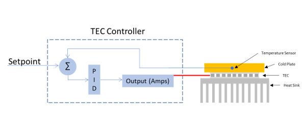
Control theory is well beyond the scope of this article. For the purposes of this article, we will focus on a specific control loop, the PID control loop. A common acronym in control loops is PID control. P stands for proportional, I stands for Integral, and D stands for derivative. The algorithms used to calculate the error correction magnitude is based on PID control and is user-adjustable to accommodate response/settling times of the control loop. An in depth understanding of PID Control can be found from the UNC Engineering Tool Kit.
WHAT IS A THERMOELECTRIC COOLER?
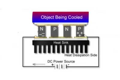
A thermoelectric cooler or TEC is a solid-state heat pump. The term "solid-state" refers to the fact that a TEC is a semiconductor based device (holes and electron flow induced by an electrical bias). The term heat pump simple refers to its ability to pump, or transfer heat from one surface to another. Current flow in one direction will cool one surface and heat the opposite. Reversing the current will reverse the heat flow.
HOW DOES A TEC COOLER WORK?
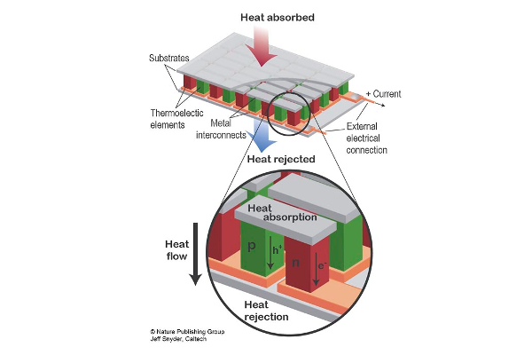
They are based on the Peltier effect, which is why they are sometimes referred to as Peltier coolers. Essentially, the Peltier effect occurs when a temperature differential is created across two dissimilar materials as a result of an electrical bias (DC current) being applied. Doped semiconductor materials (p-material and n-material) are employed and connected electrically in series as individual p-n couples. When DC current is applied, the electrons change energy states absorbing or releasing thermal energy. One side of the thermoelectric module becomes hot while the other side becomes cool. Changing the DC current reverses this affect. Peltier temperature control is simple and very effective.
Here is a quick reference on The Peltier Effect and TEC Cooling from the University of Alaska.
Shop In-Stock & Quick-Ship TEC Controllers from Leading Brands »
HOW IS A TEC USED IN A TEMPERATURE CONTROL APPLICATION?
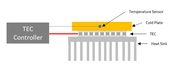
In a very basic scenario, you need a heat source (the object which needs to be cooled), a TEC / Peltier module to transfer the heat, a heat sink to absorb the heat and DC current source to bias the TEC module. These parts are configured as shown in the Temperature Controlled Mount figure below:
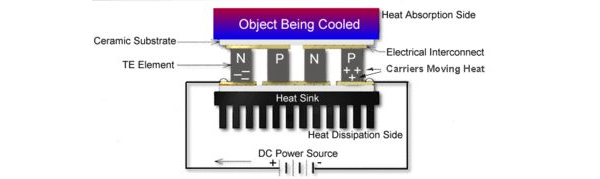
There are many considerations when designing the configuration show above. The scope of this article is focused on the selection of a properly sized TEC and heat sink along with the appropriate temperature sensor and the TEC Controller. But remember that all of the parts need to be chosen correctly to achieve optimal thermal control performance.
AN OVERVIEW OF TEMPERATURE SENSORS:
We will discuss TEC controllers in the following sections, but first you will need some background information on the feedback element in electronic TEC based temperature control systems. The feedback element is the temperature sensor. These are components that react to temperature with a change in electrical response (resistance, current, voltage).
The most common temperature sensor is the thermistor. The thermistor is a semiconductor resistive element which reacts to a change in temperature with a change in it's resistance. These can be negative or positive coefficient devices. In a negative coefficient thermistor (NTC), the resistance increases with decreasing temperature and vice versa. Typically a thermistor performs within a limited temperature range of about 50 °C around a specified base line temperature. There are solid state temperature sensors as well. A solid state temperature sensro is a circuit consisting of transistors and resistors configured in a unique way in a small package with an electrical output proportional to temperature. Solid state temperature sensors generate a more linear response to temperature changes than thermistors and cover a wider temperature range. They are often referred to as IC sensors. Their are some IC sensors which can measure temperature changes from -55 °C to +150 °C range.
CHOOSING THE BEST TEC CONTROLLER FOR YOUR APPLICATION:
Temperature controllers vary in form, function, output power and price. They are optimized for very specific applications applications, from laboratory use to OEM products requiring precision TEC based temperature control of electro-optic devices.
Shop In-Stock & Quick-Ship TEC Controllers from Leading Brands »
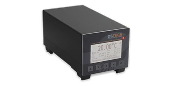
At the top end of the market (form, features and price) are benchtop instruments. These are predominantly found in research labs and production environments which require "high end" features such as computer control through a digital interface such as Ethernet, USB or GPIB. They typically have a front panel display for readout of temperature, with front panel control knobs and buttons for the user to input the control loop and sensor parameters. They can also accept inputs from a variety of temperature sensors and output the TEC current through a standard connector on the instrument’s rear panel.
Shop In-Stock & Quick-Ship TEC Controllers from Leading Brands »
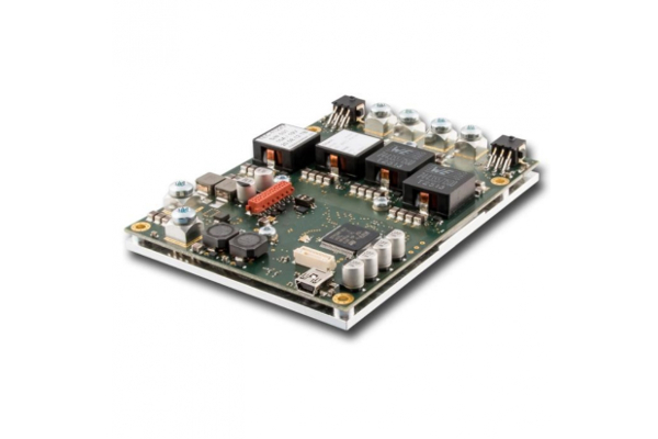
OEM modules are compact in size and are commonly integrated into systems or products which have limited physical space for a controller. OEM TEC Controllers typically operate from an independent DC power supply. They have digital or analog input/outputs for set-point temperature, current limit and adjusting PID values. They typically include all the features of a benchtop TEC controller minus the front panel adjustments. Many OEM TEC controllers also have a remote interface such as USB or RS-232. Manufacturers usually have a base model that is available for purchase in low quantities. For custom integration they can typically add new features (think multiple temperature sensor inputs) or remove features to reduce cost.
COMPONENT LEVEL TEC CONTROLLERS:
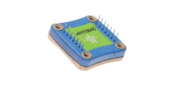
Controllers are also available at the component level. This allows for integrating a TEC controller on to a PCB assembly. These perform all of the functions of a temperature controller module in terms of TEC current output and sensor input, but many parameters such as temperature set-point and loop gain are often set externally through pcb mount trim pots or discrete resistors and capacitors. They provide input pins for multiple temperature sensors and output pins for TEC current.
HOW TO SELECT THE BEST TEC CONTROLLER:
Accurate and stable temperature control will depend on a number of system design parameters. These include selecting the correct TEC module, heat sink, temperature sensor, and the controller.
● Selecting a TEC Module (Peltier Element) - To properly select the best Peltier element, you first must understand the thermal load. This is the heat load of the device to be cooled, plus the heat transfer from the environment, plus any heat generated by the peltier device itself. Its important to remember that Peltier / TEC coolers are not 100% efficient. Not all of the electrical energy transfers heat from one surface to the other. The operating environment must also be fully understood and accounted for in the design. Meerstetter Engineering has put together a Design Guide on TEC Peltier Systems and you can also find further information from various Peltier element manufacturers.
● Checking the TEC Controller Output Current/Voltage - The TEC module you select will provide you with the maximum current and voltage for the module on the data sheet. This information is what you will use to help properly select your TEC Controller. TEC’s can be over-driven! This leads to device failure. Also, under-driving them can lead to poor system performance. It is important to properly select and limit the current and voltage from your TEC Controller.
● Selecting a Temperature Sensor - As previously discussed, there are many temperature sensor types available. For laser diodes, the most common is the NTC thermistor. NTC thermistors are used because they are inexpensive and small in size. One limitation of thermistors is their relatively small temperature range. First, you should define the temperature range over which you will operate so that you can select the best thermistor. At room temperature (20 °C), the 10 kΩ is the most common thermistor. Second, you need to check that the measurement circuit of your TEC controller can measure the resistance range you expect to operate in based on your temperature. An application note titled selecting and using thermistors for temperature control provides a more thorough overview of how to select a thermistor.
If you are designing a system which requires a wide temperature range, the AD590 (Current Changes as Temperature Changes), LM335 (Voltage Changes as Temperature Changes) and RTD (Resistance Changes) sensors have a wider temperature range. However, they are typically more expensive and/or have larger packages.
● Checking the TEC Controller Sensor Input - Most TEC controllers will offer a minimum of one thermistor input which supports 10 kΩ sensors. More advanced controllers will also support current, voltage or RTD sensors.
● PID Auto Tune - What is PID Auto Tune? Many TEC Controllers now offer an auto-tune feature for setting up the PID control loop. The firmware of the controller will automatically determine the best PID values for your thermal load and temperature set point. PID Auto Tune will reduce your set-up time and provide stable temperature control.
LIST OF TEC CONTROLLER MANUFACTURERS:
- Meerstetter Engineering
- Newport Corporation (MKS)
- Thorlabs
- Wavelength Electronics
- OptLasers
- TE Technologies
- Analog Devices
- Ferrotec
- Analog Technologies
Once you have selected your Peltier element, defined the maximum power to the Peltier required to achieve your desired temperature set-point, and chosen your temperature sensor, you are ready to select the best TEC controller: Shop In-Stock & Quick-Ship TEC Controllers from top brands ».