Home > Laser Diode Drivers > OptLasers > RLS/HPLDD-60A-24V
60 Amp Low Cost, High Power Laser Diode Driver Circuit
$450.00 sku / item#: RLS/HPLDD-60A-24V ships: This Product Is Currently Unavailable
Key Features
- Up to 200 Watts Output Power
- Up to 60 Amps Drive Current
- Simple, Reliable and Affordable Driver
- Offered by: OptLasers, a Laser Lab Source Marketplace Seller
Sold & Supported in North America by: LaserDiodeSource.com, part of the Laser Lab Source Marketplace Group
Product Warranty
All products purchased from Laser Lab Sourceare sold with a full one-year warranty. See terms & conditions for full details.The Laser Lab Source group websites include:- LaserDiodeSource.com
- LaserLabSource.com
- LaserDiodeControl.com
Customers Also Considered:
| MODEL | RLS/HPLDD-60A-24V |
|---|---|
| PRICE | $450.00 |
| Electrical Specifications | |
|
|
| Mechanical Information | |
|
|
Product Overview:
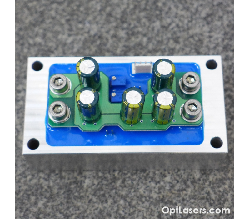
60 Amp Low Cost, High Power Laser Diode Driver Circuit
This 60 amp driver is a professional high power driver dedicated to powering infrared laser diodes.
This affordable module offers a modulation of the drive current with frequency up to 5 kHz. If you need higher modulation frequency, please inquire about the 20 kHz version of this product. It can work with 20 Watt, 40 Watt, and 60 Watt CS-mount 808nm, 940nm and 980nm laser diodes. It also works with many other similar diode types. With this driver you can power one diode or several diodes in series. Also, this module can be used for one diode stack which requires high operating voltages.
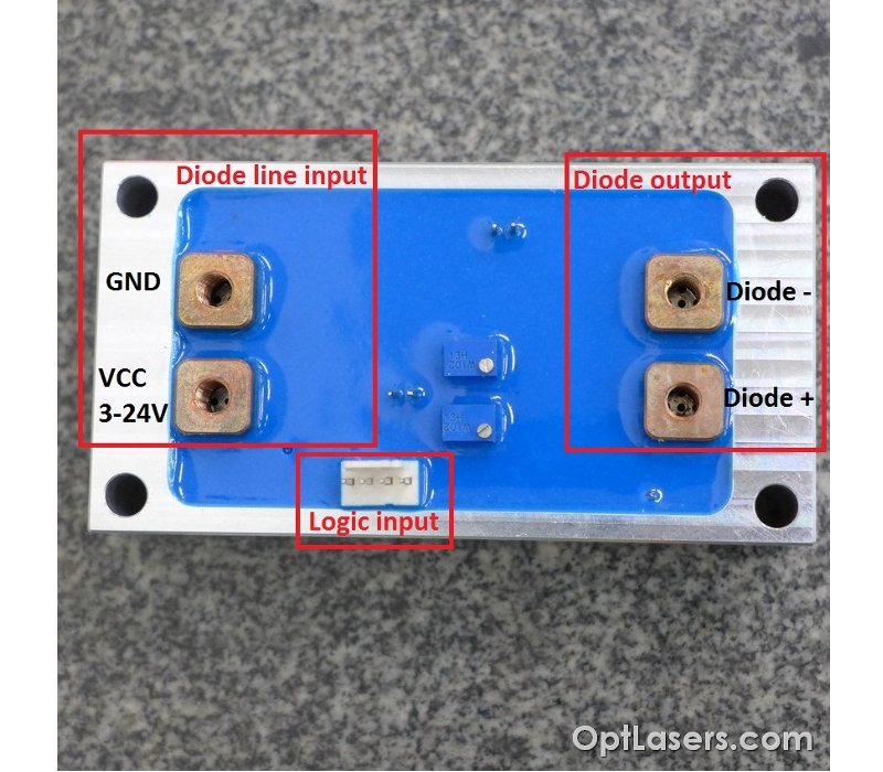
Please contact Laser Lab Source or Opt Lasers for detailed instructions on how to choose the maximum input voltage and for the operating manual. Separate laser diode supply voltage inputs and logic input voltages allow these units to minimize the switch on resistance of a power MOSFET. The inner layer of the heat sink is made of copper and helps in fast heat transmission and power dissipation. The outer body of the heat sink base, made of aluminum, is isolated from all signals on the driver including the ground signal. This allows the user to mount the driver directly to the metal chassis of a product in case additional cooling is needed.
High Power Laser Diode Driver Operating Suggestions
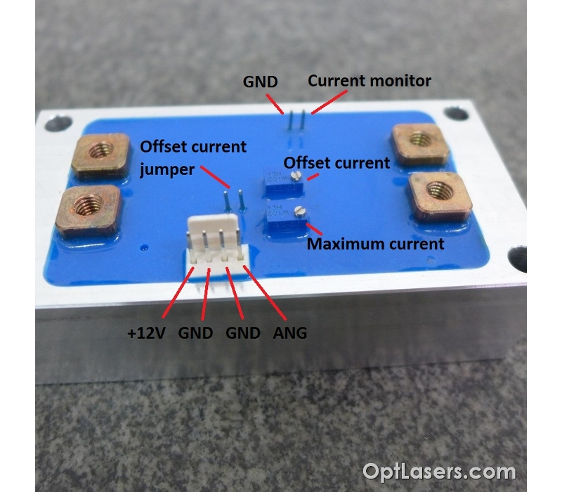
These drivers offer very high current levels flowing through the output stage paths. In order to keep the voltage drop at the output stage to a minimum, there is no reverse polarity protection. This was done to reduce the costs associated with heat sinking and waste power management. In order to ensure maximum protection for the laser, we recommend mounting a LASORB component close to the laser diode. Another option would be to mount a high power silicone diode in a reverse fashion in close proximity to the load. The high power driver body is isolated from all of the control signal paths so it can be mounted directly to the metal heat sink. The analog input is protected by a five volt zener diode to protect against over-voltage. But caution should be taken not to exceed the specification for this analog input.
The supply voltage required for the driver is dependent on the number of devices connected in series. For a single laser diode, the requirement input voltage should not exceed 5V. For 2 devices connected in series, the maximum input voltage will be approximately 8 volts. The calculation of the maximum required input voltage is given by the formula: VCC laser diode max = (the number of diodes in series) multiplied by (each of the diodes operating voltage) + 4 volts. The required logic supply is 12 volts. This power supply should be in place before the user applies power to the laser. The ground of the laser diode current path and the ground of the logic input are connected inside the driver. The user should always connect the ground of the current to the laser diode path directly to the ground of the power supply unit with the appropriate gauge wires. It is recommended that the user choose a high quality DC power supply with low ripple voltage and low noise. The user can add a capacitor to the input. Compatibility should be checked first with the PSU data sheet.
Why do Scientists & Engineers Choose Laser Lab Source?
-

Get DIRECT, Fast Tech-Support from the Product Engineer, No Sales Person in the Middle
-

Get the Lowest Price, Factory Direct, No Mark-Up's, Suppliers Post their Own Price
-

Get a 30 Day Evaluation Period with No Risk Return on Most Products, Check Availability