Home > Laser Diode Drivers > OptLasers > RLS/HPLDD-5A-48V
5 Amp, 48 Volt OEM Laser Driver Circuit PCB for Running Multiple Laser Diodes in Series
$750.00 sku / item#: RLS/HPLDD-5A-48V ships: Request a Quote for Current Ship Date
Key Features
- Affordable Laser Driver Circuit with Integrated Laser Protection Features
- Laser Output Current Range up to 5 Amps, 48 Volts
- Integrated Soft-Start Ramp to Current Set-Point and Current Limit
- Current Limit Adjustment with Trim Potentiometer
- Offered by: OptLasers, a Laser Lab Source Marketplace Seller
Sold & Supported in North America by: LaserDiodeSource.com, part of the Laser Lab Source Marketplace Group
Product Warranty
All products purchased from Laser Lab Sourceare sold with a full one-year warranty. See terms & conditions for full details.The Laser Lab Source group websites include:- LaserDiodeSource.com
- LaserLabSource.com
- LaserDiodeControl.com
Customers Also Considered:
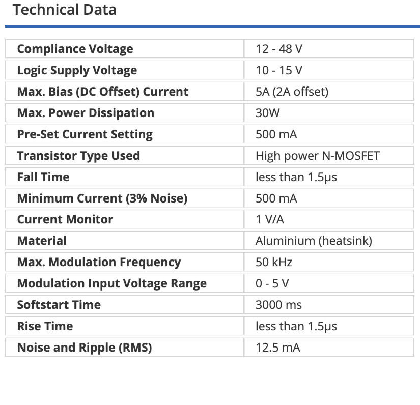
| MODEL | RLS/HPLDD-5A-48V |
|---|---|
| PRICE | $750.00 |
| Specifications | |
|
|
| Modulation Specifications | |
|
|
| Protection Features | |
|
|
Product Overview:
Affordable Laser Driver Circuit
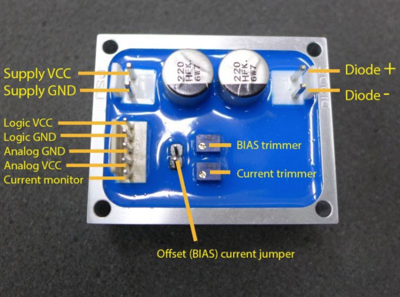
Single channel 5 A, 12-48 V, 50 kHz high voltage and power laser diode driver. The driver has two independent power inputs for logic and laser diode part of the driver which allow choosing proper power supply unit for a diode line. Two potentiometers allow to set maximum operating current and offset current usually needed for IR laser diodes. Additional monitoring output is giving feedback signal.
About the HPLDD-5A-48V
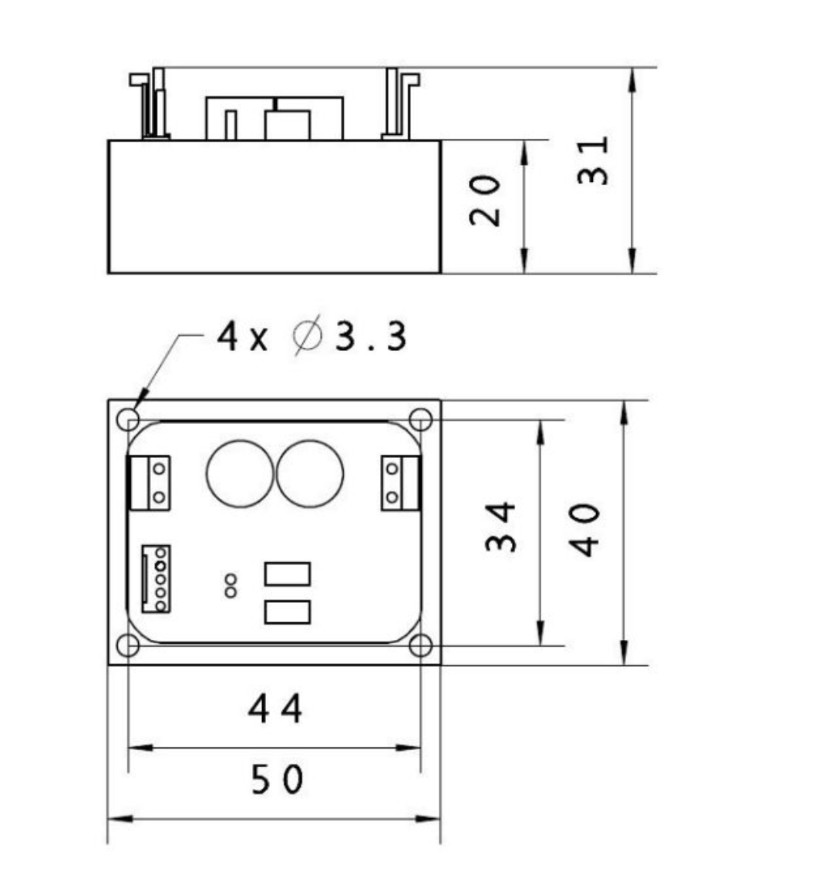
The HPLDD-5A-48V Laser Diode Driver is the professional high-power driver designed for infrared laser diodes. It is possible to modulate the current with frequency up to 50 kHz. Laser controller can work with every infrared laser diodes. It is especially dedicated to stacked laser diode systems where diode operating voltage is high (up to 48 V). While operating with stacked laser diodes proper supply voltage must be ensured. In the recommendation section, there is a formula for maximum input voltage. Separate laser diode supply voltage input and logic input voltage allow to minimizing the switch-on resistance of a power MOSFET. The outer body of a heat sink, made of aluminum, is isolated from all signals of the driver, including GND signal. It allows mounting the driver directly to the metal components in case of additional cooling needed. Two potentiometers are used to set the values of maximum diode current and bias current.
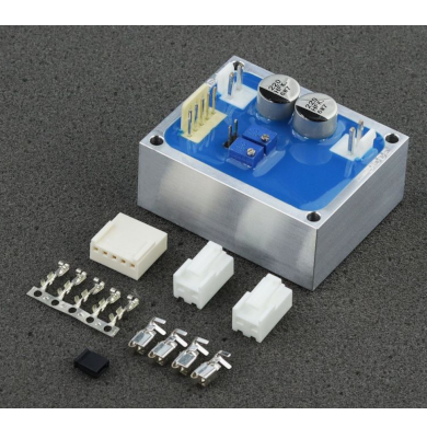
Attached to the laser diode controller are connectors and pins which are used to power and control the unit. We can also provide the proper DC power supply unit on request. Please feel free to contact us with any questions. The voltage input signal is measured, and when absent the driver will automatically shut-down the output to the laser diode.
DE Power Supply Recommendations & Connection
The DC supply voltage range depends on the laser diode system power requirements. The DC supply voltage input power level should not be greater than 5V over diode specified operating voltage. VCC DIODE MAX = (Number of diodes in series) X (Each diode operating voltage) + 5 V. For example, when using stacked laser diodes with a required operating voltage draw of 40V, the maximum supply voltage is 45 V. The user should always power the logic with 12V before applying power to the laser diode power input. Because the GND of the diode line and GND of the logic input are internally connected inside the driver, the user should connect the GND of the diode line directly to the GND of a PSU not to cause a current path through logic GND paths. The driver is provided with 3 second soft-start which appears after connecting a laser diode line to the PSU. Always use a high-quality DC power supply unit with low ripple voltage. Adding a large capacitor at the driver input is recommended.
The user should use caution not to cause a short circuit between the + VCC of the power supply and -GND of the logic input or monitor input, as GND logic paths can be irreparably damaged. Modulation input can be used as TTL input with its logic levels of 0 V and 5 V or as an analog input. Analog modulation means that by using 2.5 V on ANG input you get 50% output power, analogically by using 4 V you get 80% output power, etc.
We recommend the use of power cables with the cross-section of at least 1.5 mm2. The current monitor is 1 V/1 A. The driver should not be tested with resistive load. To test the driver properly one should use Zener diode or similar device.
Laser Diode Driver Protection
In order to provide optimized performance and speed, the driver is not protected against reverse polarity connection of the DC power supply. Please use caution and care when connecting the DC power supply. We recommend using a LASORB protection device mounted close to the laser diode. The driver's body is isolated from all signals of the driver and can be mounted directly to the metal heat sink or other metal parts with the use of 4 x fi 3.3 mounting holes (raster 44 x 34 mm). The analog input is protected by a 5V Zener diode to prevent damage from over-voltage. The driver is fitted with a 3 second soft-start current ramp designed to protect laser diodes against switch-on transient effects.
Why do Scientists & Engineers Choose Laser Lab Source?
-

Get DIRECT, Fast Tech-Support from the Product Engineer, No Sales Person in the Middle
-

Get the Lowest Price, Factory Direct, No Mark-Up's, Suppliers Post their Own Price
-

Get a 30 Day Evaluation Period with No Risk Return on Most Products, Check Availability