Home > Laser Diode Drivers > Maiman Electronics > SF6250
$1981.00 sku / item#: SF6250 ships: Request a Quote for Current Ship Date
Key Features
- Industry Leading 4-LEVEL Laser Diode Protection:
- Current limit; user can utilize redundant limit setting by using on-board trim pot and/or digital/analog controls
- Power surge, over-voltage, and over-current transient protection through on-board crowbar circuit shunt
- Soft-start current ramp
- 10K thermistor input for current shut-down if laser exceeds a customer specified temperature
- Driver Control Methods:
- Analog Control Signals Input
- On-Board Trim Pots
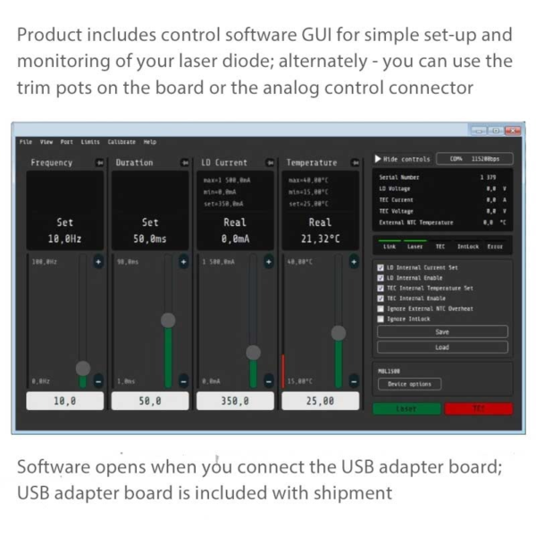
- Digital Controls: RS-232 / UART / and USB (options) $35.00 / Includes GUI Software
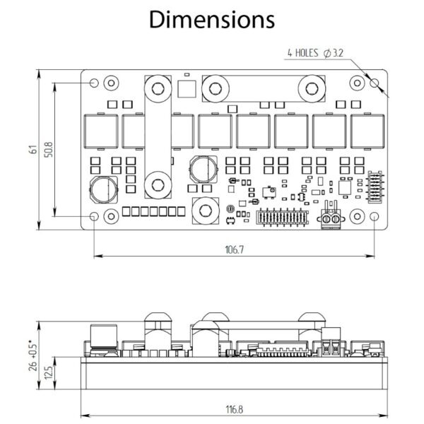
- Size: 120mm x 58mm x 30mm || Very High Efficiency ~ up to 97%
Product Warranty
All products purchased from Laser Lab Sourceare sold with a full one-year warranty. See terms & conditions for full details.The Laser Lab Source group websites include:- LaserDiodeSource.com
- LaserLabSource.com
- LaserDiodeControl.com
Price and Delivery Quote
Buy Now / Add to Cart
Customers Also Considered:
| MODEL | SF6250 |
|---|---|
| PRICE | $1981.00 |
| LASER DIODE CURRENT & VOLTAGE | |
|
|
| LASER DIODE PROTECTION | |
|
|
| DIMENSIONS AND WEIGHT | |
|
|
| USER INTERFACE | |
|
|
| REQUIRED DRIVER POWER SUPPLY (INPUT) | |
|
|
| SHIPPING KIT (INCLUDED PARTS) | |
|
|
| WARRANTY PERIOD | |
|
|
Product Overview:
250 Amp High Power Laser Diode Driver Module Overview
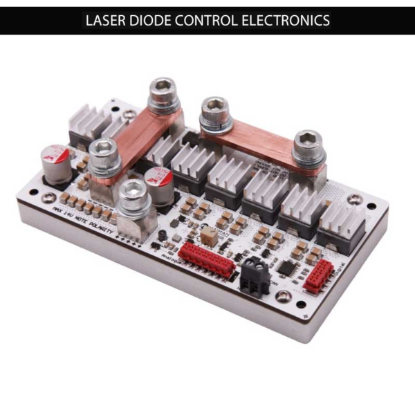
The Model 6250 is a precision high power, small form factor CW constant current source driver for laser diodes. In addition to multiple laser diode protection circuits, these modules deliver high stability at power levels up to 250 Amps with low ripple. They are offered on a thermally optimized aluminum base plate to assist with efficient heat dissipation. This driver module was designed to be easily mounted onto a thermally conductive surface with enough heat sink capability to dissipate the required waste heat. These 250 Amp, 10 Volt high performance OEM modules are an ideal choice for integration into high power laser systems used for materials processing and medical equipment applications.
Review of High Power Laser Diode Protection Features
These high current drivers provide protection features which are simple to set-up and more than adequate to protect your diode laser. They include an over current protection circuit with a user adjustable limit, a soft-start current ramp, and an over-temperature shutdown. Additional features to protect your high power device include reverse current protection and crowbar circuit protection. The crowbar circuit is a fast shorting clamp which is activated in over-current, open circuit and over-temperature events.
Multiple Protection Features and the Crowbar Clamp Protection Circuit
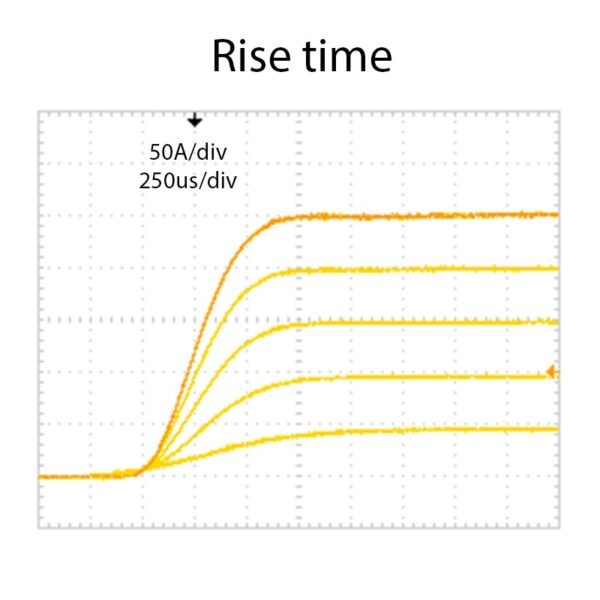
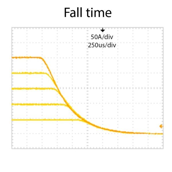
The modules are initially enabled by applying an active high 3.3V ~ 5V DC compatible logic input signal. The driver sources current and begins to operate when the 5V input enable pin is high. To ensure that the current enable is applied without overshoot, a slow start sequence initiates when the enable pin is set high. The enable pin can also be used in the quasi-CW mode. The output current is set by applying an analog signal to the current set pin on the control connector. The current set pin can be used for analog modulation by applying sign wave, square wave or ramp signal. The output may be pulsed by applying a TTL square signal to enable pin. The minimum pulse duration 500 microseconds. These high power drivers offer a highly reliable crowbar clamp to short the current and disable power to your laser diode. There is a pin on the control connector which shows the crowbar protection circuit status. The crowbar will short the output while the module is in an over-current shutdown or an over-temperature shutdown mode.
Driver Safety Interlock, Current Monitoring and Voltage Monitoring
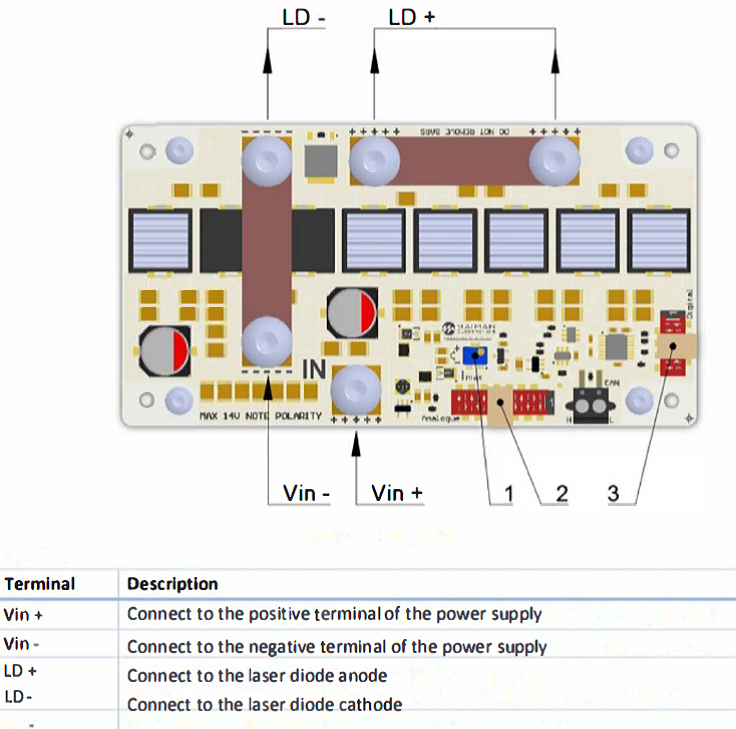
These modules have an interlock pin which must be connected to the ground order for output current to be enabled. The safety interlock is used to shut-down the module with a logic high signal triggered by and external interlock trigger such as a door to the lab or an external over-temperature circuit. These modules also have an on-board temperature sensor which will shut-down the output when the temperature exceeds a pre-set temperature. The output voltage of the driver can be monitored by a linear scaled voltage monitor output, 0~1V. The voltage is measured between LD+ terminal and GND. The current can be monitored by a linear voltage output, 0~1V = 0~3A within +/-2%.
Why do Scientists & Engineers Choose Laser Lab Source?
-

Get DIRECT, Fast Tech-Support from the Product Engineer, No Sales Person in the Middle
-

Get the Lowest Price, Factory Direct, No Mark-Up's, Suppliers Post their Own Price
-

Get a 30 Day Evaluation Period with No Risk Return on Most Products, Check Availability

