HOW TO CHOOSE A PULSED LASER DIODE DRIVER
Learn the Basics of Pulsed Drivers for Laser Diodes

Author: Stephen Gwinner, Laser Lab Source | Updated: December 30, 2019
QUICK NAVIGATION:
- What is a pulsed laser diode driver?
- Common applications
- The 5 baseline specifications to help filter your selection choices
- Start with your laser diode package
- What type of laser diode are you pulsing ~ DFB, DBR, or Grating Stabilized?
- What are the most common problems?
- Impedance matching
- Evaluate scope plots before you buy
- How is the pulse generated?
- Can I just use a voltage pulser?
- Who manufactures pulsed drivers for laser diodes?
INTRODUCTION:
Choosing a pulsed laser diode driver for your application can easily turn into a multi-day project. The design and manufacturing of fast pulsing current sources specifically for semiconductor lasers is still a highly fragmented market controlled by a handful of specialty companies. Not only is it difficult to find the companies who are making these drivers, it’s often even more difficult to get timely information from them which will help you triangulate which product best fits your needs. This article will hopefully provide you with a basic understanding of the most important factors to consider when making your choice and a list of the top manufacturers of pulsers. It will also provide an overview of which specifications are most important to check when you purchase a driver. Finally, it covers some of the basic design pricinples to hopefully help you do a better job selecting the best product for your specific application.
WHAT IS A PULSED LASER DIODE DRIVER?
To understand the basic building blocks of a semiconductor laser driver, please refer to our article on continuous wave drivers ». A pulsed laser diode driver is a voltage controlled constant current source which is designed to deliver a repeatable set of current pulses at a set output level over user defined time intervals. Their output to the laser is defined in units of amplitude and time. The type of driver we are discussing in this article delivers time units in the 100's of picoseconds, nanosecond and microsecond pulse width range, and frequencies in the range of single shot to 500 MHz.
The output current amplitude and the pulsing time parameters typically are the only parameters that you can set and adjust. You will typically not see an adjustment for output voltage. But manufacturers will specify the voltage, usually referred to on data sheets as the compliance voltage. This is the available range of output voltage of a constant current source to the load. It is the total amount of voltage a current source will reach as it attempts to produce the desired current. The job of a constant current source is to deliver a precisely set current amount, so as it attempts to produce the desired current it will source voltage following Ohm’s law. You can read more about designing pulsed laser drivers in the Analog Modules tech-notes library ».
COMMON APPLICATIONS:
Applications that require drivers in the 100's of picosecond through single digit microsecond pulse width range include fiber laser seeding, sensing, range finding, LiDAR and emerging medical applications such as tomography as described in this article on pulsed laser diode ».
THE 5 MOST IMPORTANT SPECIFICATIONS TO CONSIDER WHEN CHOOSING A PULSED LASER DIODE DRIVER:
When you are looking at the data sheet, and you immediately skip from the product photo to the table of spec's as we all do, you are looking for a few key spec's to help you quickly filter to the best product fit. In addition to your laser package style, which is discussed below, these five clearly defined specifications will help you filter your selections quickly:
» Current Amplitude Range
» Pulse Width Range (picoseconds, nanoseconds or microseconds)
» Frequency Range (usually Single Shot to X MHz)
» Duty Cycle Limit (ie limited to 50% duty cycle)
» Compliance Voltage Range (usually in the 3V~10V range)
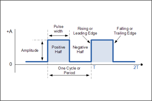
The current amplitude is straight forward. So the three time parameters are the variables you may want to check first. Here is quick review of the time paramaters frequency, duty cycle and pulse width. This review is very basic, but helpful if you need a refresher:
START WITH YOUR LASER DIODE'S PACKAGE STYLE AS YOUR FIRST AND PRIMARY SELECTION FILTER:
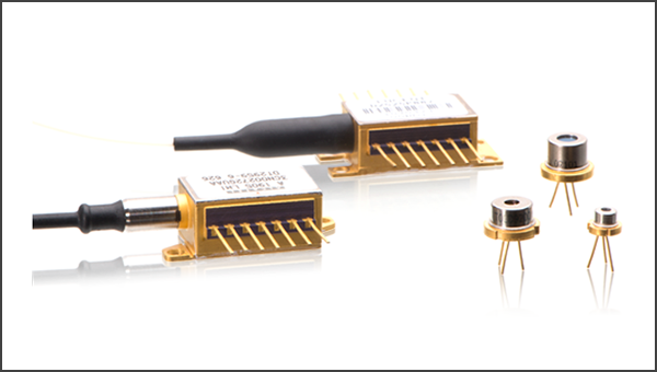
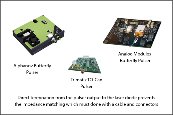
Even though it’s fairly intuitive, you should consider starting with your laser diode package style and working backwards to the pulser, using the package style as your first selection filter when you are trying to find the best fit driver. Commercially available pulser’s are often made for a specific laser package style. This means that they will usually have interface mounting pads or pins which are optimized for a butterfly package or a TO-Can package. And some have high power bracket connector outputs for high power fiber coupled laser modules (10’s or 100’s of Watts). As we will discuss below, because impedance matching is such a difficult challenge in fast pulsing applications, the interface from the pulser to the laser is a major selection variable. If the manufacturer does not have photos showing the connection to the package style you will work with, I recommend you move on and find a manufacturer that has photos.
SPECTRAL EMISSION CONSIDERATONS WHEN PULSING A DFB, DBR OR FGB STABILIZED LASER DIODE:
When choosing a pulser, it is important to keep in mind the response time of the type of laser diode you intend to pulse. For example, with fiber Bragg grating stabilized lasers (FBG), there is an inherint time period (lag) required for the laser to lock onto its Bragg locking element. This locking is almost immediate for a DFB or DBR, but it often requires more than 100 nanoseconds for an FBG based laser. When pulsing a Grating stabilized laser diode, the first nanosecond produces a broad emission spectrum as if there were no Bragg grating present. Some suppliers such as Lumics offer an intermediate solution that offers the Bragg closer to the chip which reduces this locking time lag to a few nanoseconds.
WHAT ARE THE MOST COMMON PROBLEMS ENCOUNTERED WHEN PULSING A LASER DIODE?
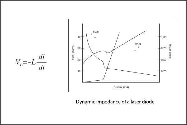
The most common problem encountered when pulsing a laser at high repetition rates is pulse degradation, ie overshoot and ringing, caused by improper impedance matching. Current sources inherently have a high output impedance and laser diodes have very low impedance. The most important requirement of proper impedance matching is matching the impedance of the load to the impedance of the transmission line. When the impedance levels are not matched, inductance theory quickly comes in to play, and not in a helpful way. The inductance of laser diodes ranges from a few nanohenries to tens of nanohenries. As we all remember, v is the voltage in volts, 𝐿 is the inductance in henrys, and 𝑑𝑖/𝑑𝑡 is the rate of change in current over a specific period in amperes per second. The voltage increases with the inductance and with the rate of the change of the current. Energy stored in the inductors’ magnetic fields during the pulse has to be released when the pulse ends. This creates a voltage, which in turn creates a new current, which in turn creates a new magnetic field on the transmission path. This goes on and on in a “loop”. This inductance loop shows up as “ringing” on the pulse waveform and on other distortions to the pulse shape.
In order to avoid the pulse degradation from the inductance loops, the impedance from the pulser launch pads through the interface cable to the device under test must be optimized. This includes the termination of the cable onto the laser diode pins. If the impedance of the various parts of the current transmission line path are different, you can also see a loss of output power from the LD due to reflections of the signal at the junction points in the current path. Keep in mind that laser diode pulser’s are current sources, and current sources will not absorb reflections due to load mismatches.
IMPEDANCE MATCHING CONSIDERATIONS:
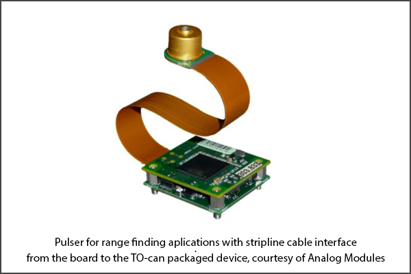
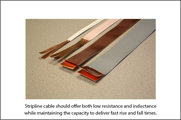
To reduce the issues described above, you first need to avoid any unnecessary hardware between the pulser and the laser diode. Whenever possible, connect the laser diode directly to the pulser board. If you have to use a cable, remember that the cable and the interconnects must offer both low resistance and inductance while maintaining the capacity to deliver fast rise and fall times. Keep the current path as short as possible (ie under 6 cm). BNC jacks, alligator clips and coaxial cables all add inductance. So they should be avoided. The most direct connection is the best connection. Many engineers use a low inductance copper strip line cable with a wide surface area (ie ½ cm), a low inductance connector and solder wick as the basis of their current path.
To match the impedance from the pulser to the laser, you can use multiple resistors in parallel to reduce the parasitic inductance. I have also read a Tech-Note which showed reduction simply by placing a resistor in series with the LD. The value needs to be equal to the difference between the output Ω of the pulser and the dynamic impedance of the diode. Calculating the dynamic impedance of a semiconductor laser is not a trivial exercise. So I highly recommend that you ask the manufacturer of the pulser about this prior to making a selection. I would contact the manufacturer and ask for their recommendation on impedance matching for the type of laser diode package you plan to pulse. Just send an email and ask them to document their suggestions based on your laser. You will most likely be logging many hours optimizing your set-up, you may as well let them shorten the learning curve.
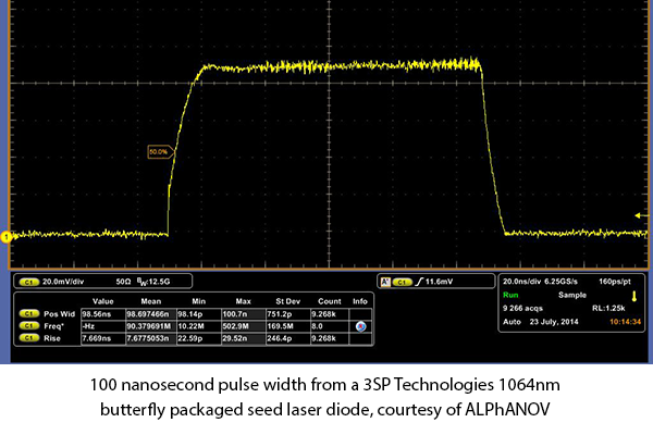
EVALUATE PULSED MODE SCOPE PLOTS BEFORE YOU BUY:
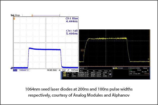
Most manufactures should have readily available scope plots which show the pulse integrity measured on a high frequency oscilloscope (100’s of MHz ~ GHz) and with a fast GHz photodetector. These scope plots should be based on a high rep. rate laser diode load (not an electrical dummy load). I recommend you look for scope plots which are taken from powering a device which is in the same package style (ie butterfly) that you plan to use.
HOW IS THE PULSE GENERATED?
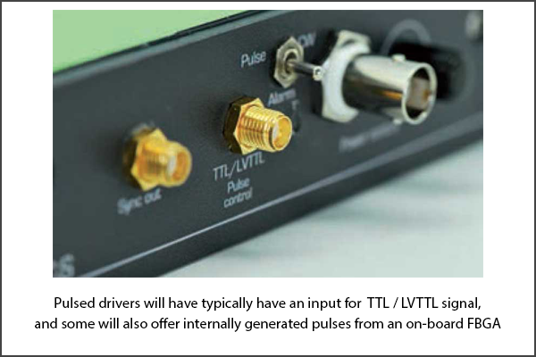
External Pulses: Drivers will usually have an input for TTL / LVTTL signal and will specify that the pulse will trigger on the rising edge. So you will need to connect a voltage pulser to this connector to trigger your current pulses to the laser. They will usually take a pulse that is in the 2V to 5V range and the input impedance is usually a 50 ohm termination. The input connector style is typically SMB / SMA. They may specify a propagation delay associated with this pulsed voltage input.
Internal Pulses: Some pulsers will also have an internal pulse generator, and some will have both internal and external. The internally generated pulse comes from an on-board field programmable gate array (FPGA) pulse generation system. You typically pay more for the additional internal function generator, so it’s a function of budget as well as convenience. A pulser will also have a synchronization output signal. This SMA output is usually an LVTTL copy of the driving signal. This driver from Alphanov » is an example of a unit that has both an external TTL input by SMA connector and an FPGA internally generated pulse genertor.
CAN I USE A VOLTAGE PULSER?
If you are working in a lab, you're probably more familiar with and have access to benchtop voltage sources. Many engineers do use voltage pulsers because they are less expensive and more common. Unfortunately, most voltage sources have a much greater instantaneous current capability than constant current sources. This capability can often result in damaging over-current transients to the diode laser. There are a few reasons for over-current transisents. But one of the primary causes is a brief break in the electrical contact path which causes the power supply to wind-up as it detects an increasing resistance. The power is then released across the load when connection is re-established. If a laser diode has a defined specification of rise time in nanoseconds, you can be pretty sure that it is going to cost over $1,000.00. So you don’t want to risk an over-current transient destroying the device under test. Also, laser diodes have a dynamic resistance. Voltage and resistance both change with current and temperature. Semiconductor lasers are highly sensitive to temperature fluctuations. Temperature fluctuations result in changes in the optical output power. So even if the voltage is held constant through the pulses, current fluctuations and resultant optical output power changes will occur. So it is much more difficult to get accurate pulsed optical power from a laser with a voltage source.
MANUFACTURERS OF PULSED DRIVERS:
There are fewer than 10 companies around the world who specialize in manufacturing commercially available pulsers. You can see a list of pulsed laser diode drivers and their manufacturers here ». Some of these products are offered for sale by the manufacturer directly through the LaserDiodeControl.com marketplace, and some are offered only from the manufacturer. Any manufacturer or supplier is welcome to upload their products to our index for free in order to help you select the best pulser for your application.