Home > Laser Diode Drivers > AeroDIODE > SHAPER-DIRECT / PULSED LASER DIODE DRIVER
Pulsed Laser Diode Driver; PULSE-SHAPER, User Designed Pulse Shapes
$6495.00 sku / item#: SHAPER-DIRECT / PULSED LASER DIODE DRIVER ships: Request a Quote for Current Ship Date
Key Features
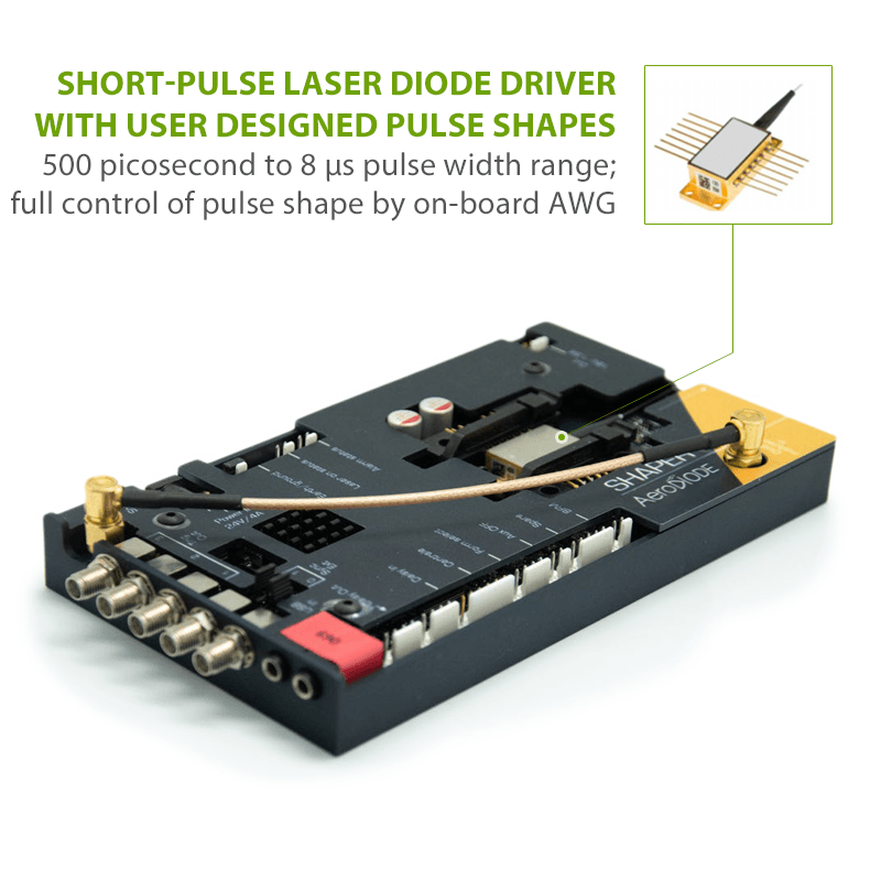
- User Designed Pulse Shapes; On-Board Arbitrary Waveform Generator (AWG) for User Customizable Pulse Shapes
- Pulse Width Range: 500 Picoseconds to 8 µsec
- 1.6 Amp Output Current, 20 MHz Repetition Rate
- Includes Laser Diode “Gain-Switch Peak” Suppression Mode
- Integrated Pre-Configured Butterfly Mounting Socket and Integrated TEC Controller
- Built-in Pulse AWG, Internal or External Triggering
- Two Models Available: Direct or External Modulation (Direct Model shown here; Inquire for Details on External Modulation Model)
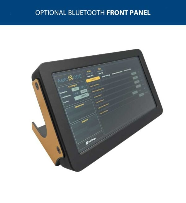
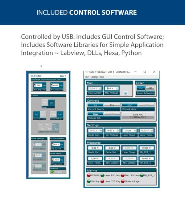
- USB Interface with Intuitive GUI Control Software
Product Warranty
All products purchased from Laser Lab Sourceare sold with a full one-year warranty. See terms & conditions for full details.The Laser Lab Source group websites include:- LaserDiodeSource.com
- LaserLabSource.com
- LaserDiodeControl.com
Price and Delivery Quote
Buy Now / Add to Cart
Customers Also Considered:
| MODEL | SHAPER-DIRECT / PULSED LASER DIODE DRIVER |
|---|---|
| PRICE | $6495.00 |
| Internally Generated Pulses Pulsed Current and Pulse Shaping Specifications | |
|
|
| Electrical SynchronizationPulse Delay Generator Outputs | |
|
|
| TEC & Butterfly Mount | |
|
|
| Specifications for optional SHAPER-EXTERNAL ModelAOM / EOM Pulsed Current and Pulse Shaping Specifications | |
|
|
| User Interface | |
|
|
| Power Supply & Dimensions | |
|
|
Product Overview:
Pulsed Laser Diode Driver | Design your Own Pulse Shapes:
This latest generation pulsed laser diode driver gives you full control over the shape of the current pulse to your laser diode. These multi-functional units have an integrated AWG (Arbitrary Waveform Generator), pulsed current source, TEC controller and pre-configured butterfly mounting socket. They also include multiple pulse delay generators for signal synchronization. These drivers allow you to completely tailor the pulse shape for your application; these units are capable of generating virtually any pulse shape with a nanosecond pulse duration. You have full control of the pulse shape through the control software and GUI.
USB Interface with Control Software with GUI:
These units come with a USB interface and control software with a simple to use graphical user interface. A DLL library for C programming as well as a hexadecimal programming protocol are both available at not additional charge. Also, there is a UART interface for industrial control applications.
Pulse Generation ~ Internal / On-Board Pulser or with External Trigger:
These pulsed laser diode drivers are designed to operate in a stand-alone mode using internal modulation, or with an AOM/EOM using external modulation. They offer a pulse shaping range from 500 picoseconds to 8 microseconds in either internal or external modulation mode. Other features include 3 outputs to allow the user to synchronize multiple devices and a 16 bit processor to provide high current set-point resolution. Also, a “Gain Switch Peak” suppression mode is included to suppress the picosecond gain switched peak which is inherent to laser diodes in short pulsing environments.
Current Source to Butterfly Package Impedance Matching Improves Your Laser Diode's Pulse Performance:
When the impedance from the pulsed current source PCB is not properly matched to the butterfly package pins, significant pulse degradation can occur. This is often seen as distortion of the laser output pulses and/or overshoot of the pulses. These pulsed laser diode drivers are designed to reduce and/or eliminate this pulse degradation by matching the nominal impedance of the butterfly packaged laser diode with the pulse transmission line. Current sources inherently have a high output impedance and laser diodes have very low impedance. The most important requirement of proper impedance matching is matching the impedance of the load to the impedance of the transmission line. The inductance of laser diodes ranges from a few nanohenries to tens of nanohenries. From inductance theory, 𝑑𝑖/𝑑𝑡 is the rate of change in current over a specific period in amperes per second. The voltage increases with the inductance and with the rate of the change of the current. Energy stored in the inductor's magnetic fields during the pulse has to be released when the pulse ends. This creates a voltage, which in turn creates a new current, which in turn creates a new magnetic field on the transmission path. This creates a “loop” which manifests as “ringing” on the pulse waveform and on other distortions to the pulse shape. The CCS current output transmission path has been carefully designed to match the current source impedance to the butterfly packaged laser diode.
Why do Scientists & Engineers Choose Laser Lab Source?
-

Get DIRECT, Fast Tech-Support from the Product Engineer, No Sales Person in the Middle
-

Get the Lowest Price, Factory Direct, No Mark-Up's, Suppliers Post their Own Price
-

Get a 30 Day Evaluation Period with No Risk Return on Most Products, Check Availability