Home > Laser Diode Controllers - (Driver + TEC) > Lasertack > LDI-TEC-4500
Request Quote sku / item#: LDI-TEC-4500 ships: This product is currently no longer available to purchase through LaserDiodeSource.com; please contact LaserTack directly for price and delivery
Key Features
- Up to 2500mA Laser Diode Bias Current Output Range
- TEC / Temperature Controller Output Power up to 2 Amps, 12 Volts
- Temperature Control Loop Pre-Set for 10K Thermistor Feedback Measurement
- Supports Modulation up to 500 kHz Analog Modulation
- Ultra-Compact / Small Footprint
- Offered by LaserTack GmbH, a Laser Lab Source Marketplace Seller
Sold & Supported in North America by: LaserDiodeControl.com, part of the Laser Lab Source Marketplace Group
Product Warranty
All products purchased from Laser Lab Sourceare sold with a full one-year warranty. See terms & conditions for full details.The Laser Lab Source group websites include:- LaserDiodeSource.com
- LaserLabSource.com
- LaserDiodeControl.com
Customers Also Considered:
| MODEL | LDI-TEC-4500 |
|---|---|
| PRICE | Request Price |
| SPECIFICATIONS | |
|
|
Product Overview:
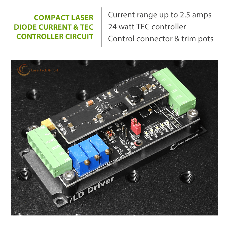
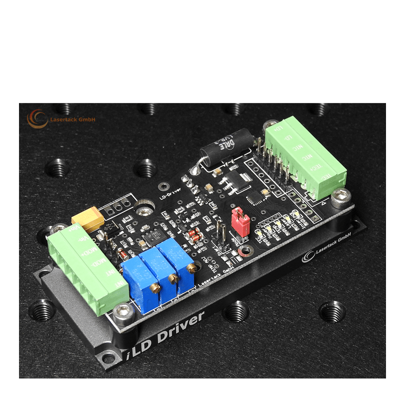
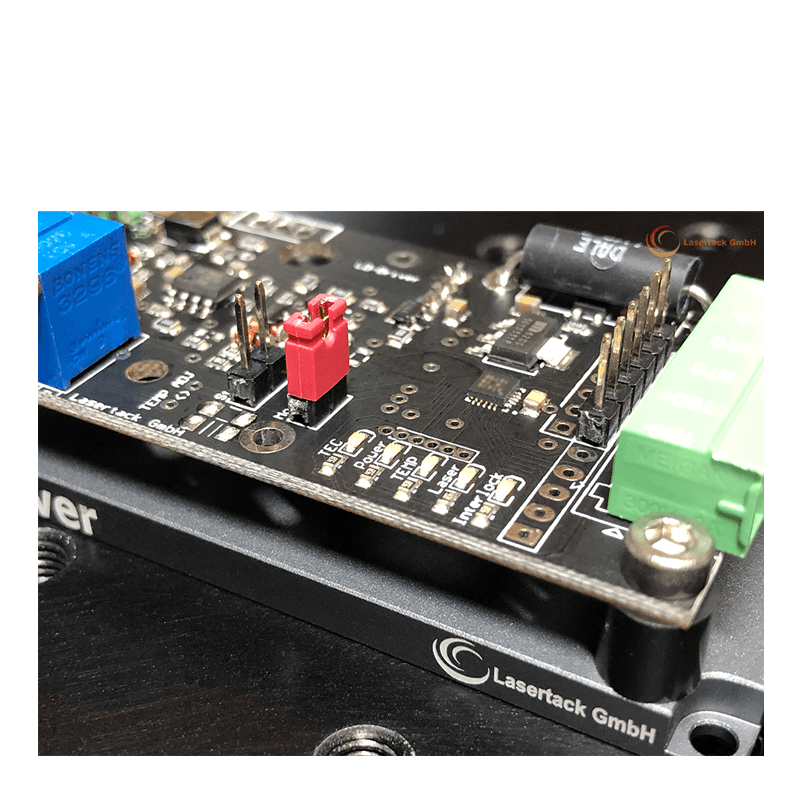
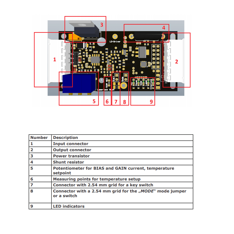
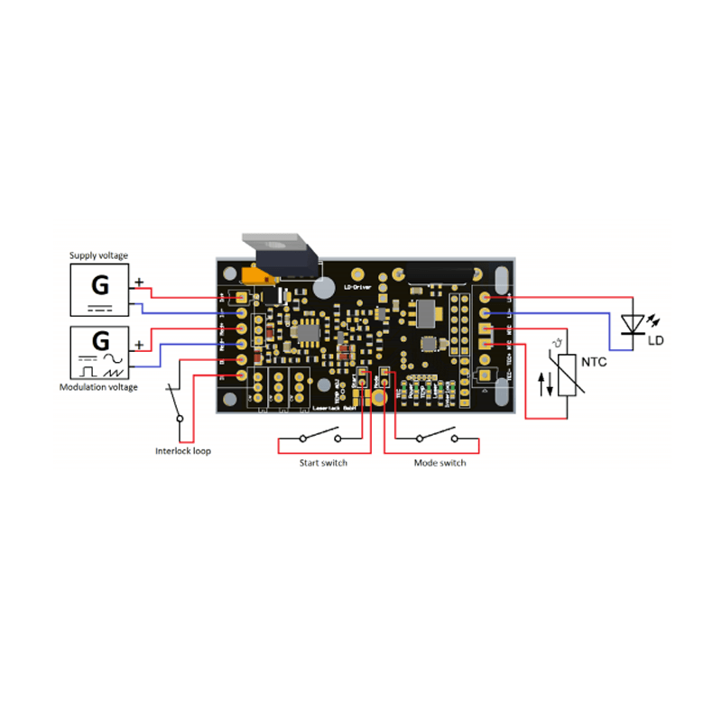
These affordable miniature laser diode controller circuits are manufactured by Lasertack, Germany, and offer a precision current source up to 2500mA and up to 2 Amps of power to a TEC cooler. They are supplied by a voltage 5 to 12 VDC power supply input and offer the user a wide modulation bandwidth of 500 kHz Analog from a voltage source of DC to 5V. They offer a fast rise and fall time specification, and a low noise specification of <1.6 millivolts. The TEC controller loop is unidirectional (cool only). and they offer a very high temperature control accuracy of 0.1°C. These controller modules were designed for high power laser diodes. KEY FEATURES: LED indicators: The LED indicators show the real-time state of all functions and the driver state. Normal condition operation or failure state mode is immediately shown by LED indicators. Temperature monitoring: With a 10Kohm thermistor temperature sensor connected, temperature monitoring is active. The measured values are used for over-temperature shutdown and for the TEC controller. Safety shutdown: The driver shuts down the output to the laser diode when over-temperature is detected or the interlock loop is broken. The LED indicators show which failure mode occurred. Active and passive interlocks: Active and passive interlock loops can be utilized. A simple door switch or a 5V interlock loop can be connected. Turn-on delay: After connecting the power supply, the driver allows the PSU to stabilize before enabling the laser output. Programmable failure treatment: In the case of a failure because of over-temperature or a broken interlock, the driver can handle the situation in two ways. It can restart the laser when the failure caused problem is solved automatically or it will wait for a restart signal. The programming is done by the shorting of of the two connector pins pairs.
Why do Scientists & Engineers Choose Laser Lab Source?
-

Get DIRECT, Fast Tech-Support from the Product Engineer, No Sales Person in the Middle
-

Get the Lowest Price, Factory Direct, No Mark-Up's, Suppliers Post their Own Price
-

Get a 30 Day Evaluation Period with No Risk Return on Most Products, Check Availability

