Home > Laser Diode Drivers > AeroDIODE > CCS-HPP / PULSED LASER DIODE DRIVER
Pulsed Laser Diode Driver; 4 Amps / 24 Volts; Adjustable Pulses from 0.5 nsec to 8 µsec; 250 MHz, Integrated Butterfly Mount
$6995.00 sku / item#: CCS-HPP / PULSED LASER DIODE DRIVER ships: Request a Quote for Current Ship Date
Key Features
- User Set Pulse Widths from 0.5 ns to 8 µs
- 4 Amp Current Range; 24V Voltage Range
- 1 Hz to 250 MHz Repetition Rate
- Integrated Pre-Configured Butterfly Mounting Socket & TEC Temperature Controller
- 24V High Compliance Voltage
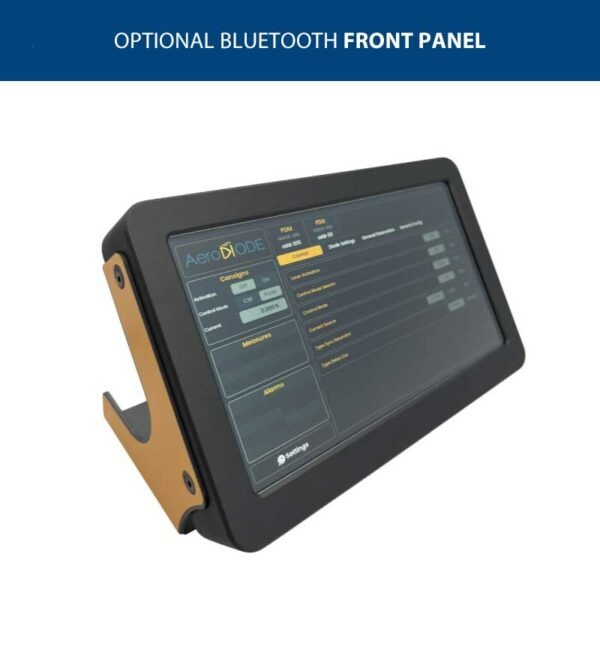
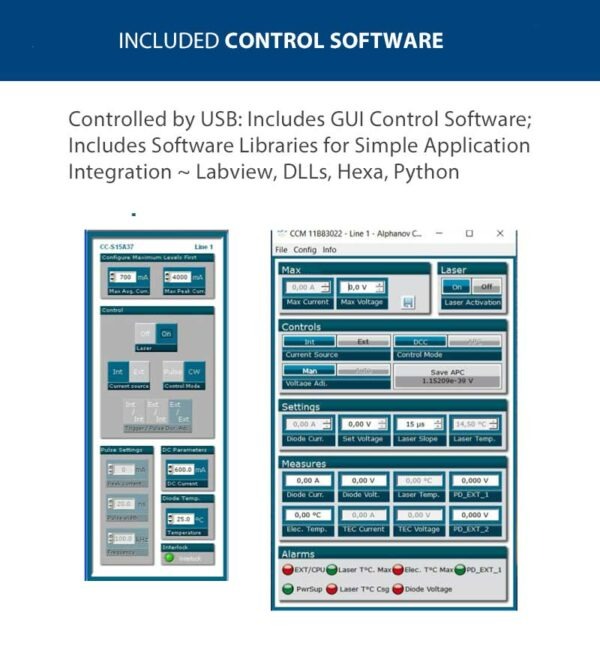
- USB Interface, Includes Programming Tools Software Suite, DLL Library and GUI
Product Warranty
All products purchased from Laser Lab Sourceare sold with a full one-year warranty. See terms & conditions for full details.The Laser Lab Source group websites include:- LaserDiodeSource.com
- LaserLabSource.com
- LaserDiodeControl.com
Price and Delivery Quote
Buy Now / Add to Cart
Choose the Pinout For Your Application,
Type-1, Type-2, or Type-2 Bias-T
Customers Also Considered:

| MODEL | CCS-HPP / PULSED LASER DIODE DRIVER |
|---|---|
| PRICE | $6995.00 |
| Pulsed Output Current & Voltage Specifications | |
|
|
| Temperature Controller & Butterfly Mounting Socket | |
|
|
| Laser Diode Protection | |
|
|
| User Interface, Power Input & Dimensions (all models) | |
|
|
| Pulse Generation Mechanisms ( 3 Modes ) | |
|
|
Product Overview:
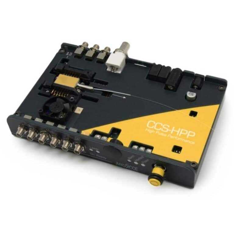
CCS-HPP High Pulse Performance Laser Diode Driver & Mount Unit
This pulsed laser diode driver and butterfly mounting module is optimized for high performance, high power pulsing with pulse width from 0.5 ns to 8 µs. These pulsed control and mounting modules deliver precision pulses which are generated internally by an on-board pulse generator, or on demand from your external TTL signal generator.
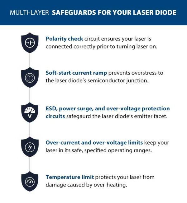
Laser Diode Protection Features
The CCS-HPP series drivers include comprehensive laser diode protection. They include an efficient TEC controller which keeps the laser temperature stable and protects it from thermal damage. The USB interface and graphical user interface offers the user complete control of the temperature and current limit parameters. The user controls pulse width, amplitude, rep. rate, temperature set point, current / temperature limits and more.
Pin Configurations
The CCS-HPP is available for industry-standard butterfly package pin configurations. Because impedance matching is a critical factor in delivering clean high speed pulse performance, the CCS-HPP unit is pre-set for your laser diode's pin configuration (TYPE-1 by default). Refer to the images above to view available pin settings. The standard configuration is the Type-1 pinout; please inquire if you require the Type-2 pin configuration.
Flexible Pulse Generation and Output Synchronization
These drivers offer the user three different pulse generation sources. The internal pulse generator; an external trigger source; or an external trigger source can be used to activate the internal pulse generator.
When using an external trigger source, the input pulse trigger is a TTL/LVTTL input voltage. The input voltage range for the external trigger is 0 ~ 3.3 Volts. These units also provide the user with a sync-out port which allows synchronization of the driver to related test equipment. This SMA output port delivers an LVTTL copy of the CC-S logical driving signal.
Pre-Set Impedance Matching Improves Laser Diode Pulse Performance
If the impedance from the pulsed current source PCB is not properly matched to the butterfly package pins pulse degradation can occur, and can hamper operating in the intended application. The degradation is sometimes seen as distortion or overshoot of the laser output pulses. The CCS pulse unit is designed to reduce and/or eliminate this pulse degradation by matching the nominal impedance of the butterfly packaged laser diode with the pulse transmission line.
Current sources inherently have a high output impedance and laser diodes have very low impedance. The most important requirement of proper impedance matching is matching the impedance of the load to the impedance of the transmission line. The inductance of laser diodes ranges from a few nanohenries to tens of nanohenries. From inductance theory, 𝑑𝑖/𝑑𝑡 is the rate of change in current over a specific period in amperes per second. The voltage increases with the inductance and with the rate of the change of the current. Energy stored in the inductor's magnetic fields during the pulse has to be released when the pulse ends. This creates a voltage, which in turn creates a new current, which in turn creates a new magnetic field on the transmission path. This creates a “loop” which manifests as “ringing” on the pulse waveform and on other distortions to the pulse shape. The CCS current output transmission path has been carefully designed to match the current source impedance to the butterfly packaged laser diode.
Why do Scientists & Engineers Choose Laser Lab Source?
-

Get DIRECT, Fast Tech-Support from the Product Engineer, No Sales Person in the Middle
-

Get the Lowest Price, Factory Direct, No Mark-Up's, Suppliers Post their Own Price
-

Get a 30 Day Evaluation Period with No Risk Return on Most Products, Check Availability