Test and Characterization of Laser Diode
Determination of Principal Parameter
Author: Kamran S. Mobarhan, Ph.D.
Newport Corporation
Introduction
It is often necessary to quantitatively assess the quality, performance, and characteristics of laser diodes. This is done through performing a series of experiments and obtaining certain significant parameters from which we can determine how well the laser diode is performing. It is then possible to establish whether or not the laser diode meets the desired specifications. The following is a brief description of the common parameters that can be experimentally determined and the techniques involved in the analysis of the raw data that lead to meaningful and easy-to-interpret results.
Output Light vs. Input Current Curve and Threshold Current:
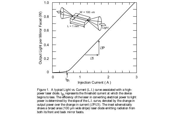
Perhaps the most important characteristic of a laser diode to be measured is the amount of light it emits as current is injected into the device. This generates the Output Light vs. Input Current curve, more commonly referred to as the L.I. curve (shown in Figure 1). As the injected current is increased, the laser first demonstrates spontaneous emission which increases very gradually until it begins to emit stimulated radiation, which is the onset of laser action. The first parameter of interest is the exact current value at which this phenomenon takes place. This is typically referred to as the threshold current and is denoted by the symbol Ith. It is generally desirable that the threshold current be as low as possible, resulting in a more efficient device. Thus, threshold current is one measure used to quantify the performance of a laser diode.
Threshold Current Density:
Threshold current depends upon the quality of the semiconductor material from which the device is fabricated and the general design of the waveguide structure. However, threshold current also depends upon the size and area of the laser device. One laser diode could demonstrate a much higher threshold current than another device and yet be considered a much better laser. This is because the area of the device can be large. A laser that is wider or longer obviously requires more electric current to reach the onset of laser action than a laser of smaller area. As a result, when comparing the threshold current values of different devices, it is more appropriate to refer to threshold current density rather than threshold current.
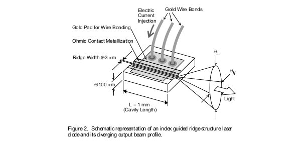
Threshold current density is denoted by the symbol Ith and is determined by dividing the experimentally obtained threshold current value Ith by the area of the laser. It is always desirable for a laser to have a low threshold current density value. Threshold current density is one of the parameters that is a direct indication of the quality of the semiconductor material from which the device is fabricated. In comparing the performance of various laser devices one must compare the threshold current density values rather than the threshold current values. In calculating the current density of the laser it is necessary to accurately measure the area of the laser through which current is being injected. This is only possible in broad area type lasers with stripe widths on the order of 100 µm or more. In such cases the area through which the current is flowing is very much the same as the area of the metallic contact of the laser. In cases of ridge lasers (Figure 2) the width of the ridge is only a few microns, while, due to current spreading, the actual width of the channel through which current is flowing could be considerably more. This makes it impractical to accurately determine current density values in cases of narrow stripe ridge lasers.
Slope of the L.I. Curve:
Just as it is desirable to reach laser action at as low a threshold current as possible, it is also desirable to get more and more light out of the device with the expenditure of as little current as possible. In other words, you want to be able to increase the input current slowly and yet have rapid increase in the output light emission. A laser diode, which has a good conversion rate of input electric power to output light power, is obviously a device that performs well. A direct measure of the ability of the device to do this is the slope of the L.I. curve above the threshold current point. This slope is denoted as ∆P/∆I and has the units of Watts per Amperes (W/A), or in the case of low power lasers (mW/mA). ∆P/∆I, the slope of the L.I. curve above the threshold current Ith, tells us directly how many Watts of power the laser outputs for every 1 Amp increase in its input current. Other important parameters are typically extracted from measurement of this ∆P/∆I slope efficiency
External Differential Quantum Efficiency:
Resulting directly from the experimental measurement of the slope of the L.I. curve is another parameter referred to as External Differential Quantum Efficiency, ηd. This is a figure of merit, measured in percentage, which indicates the efficiency of a laser device in converting the injected electron hole pairs (input electric charges) to photons emitted from the device (output light). A perfect hypothetical device that converts 100 percent of the injected current into output light with no waste in the form of heat generation would theoretically have an ηd value equal to 100%. Of course such a device does not exist in reality. We can determine the External Differential Quantum Efficiency value of a real laser diode by measuring its slope of the L.I. curve, ∆P/∆I, above threshold current. We then need to compare that to the slope of the L.I. curve of the perfect, 100% efficient, theoretical device. This is done as explained below.
One single electron has an electric charge of q, where q = 1.6x10e–19 Coulombs. One Coulomb, denoted by C, is an electric charge equal to the electricity transferred by a steady current of one Amp in one second. This means that one C/sec is one Amp. Now on the other hand, one photon, of wavelength λ, has an energy of E = h(c/λ), where h is Planck’s constant, which relates the energy and the wavelength of the photon. Remember that the unit of energy is Joule, one Joule per second is equivalent to one Watt of power.
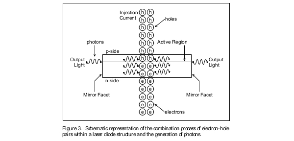
In an ideal perfect laser, the recombination of each electron-hole pair results in the generation of one photon, and additionally the photon survives its travel through the laser waveguide structure and is emitted from the device to contribute to the output light power. In a real laser, some electron-hole pair recombinations result in the generation of photons, while others result in the generation of other, undesirable, forms of energy, such as heat. In addition, not all the photons generated inside the laser are emitted from the device. Some of them are reabsorbed by the structure of the laser (Figure 3). As a result, in the case of an ideal perfect laser an electric charge of q Coulombs results in h(c/λ) Joules of output optical energy. This means that a current of q Coulombs per second (Amps) results in a light power of h(c/λ) Joules per second (Watts). Thus, the slope of the L.I. curve of an ideal, perfect, laser emitting at a wavelength of λ would theoretically be (hc)/(λq), where as mentioned, h is Planck’s constant, λ is the wavelength of generated light, and q is the electric charge of a single electron. Note that wavelength λ of light is related to its frequency υ through the relationship υ = c/λ, where c is the speed of light.
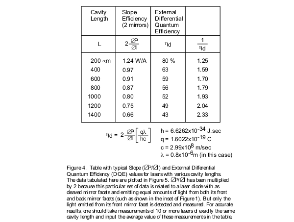
Now, to compare the efficiency of a real laser, being tested in the laboratory, to the ideal perfect laser, we can compare the slopes of their L.I. curves. This means, that the efficiency of a real laser, in converting input current to output light, is the ratio of its associated ∆P/∆I parameter to hc/qλ. Since both terms ∆P/∆I and hc/qλ have the same units of Watt/Amp, the resultant term: (∆P/∆I) / (hc/qλ) is a unit-less parameter given in a percentage form. This is what is referred to as the External Differential Quantum Efficiency, ηd, and is equivalent to (∆P/∆I) / (hc/qλ). To calculate ηd, simply measure the slope of the L.I. curve in units of Watt/Amp and multiply it by qλ/hc
Note that in doing this, we took into account the fact that photons of different wavelength have different energies. For example one blue photon (the photon of blue color radiation, with wavelength in the 400 nm range of the spectrum) has more energy than a red photon (the photon of red color radiation, with wavelength in the 600 nm range of the spectrum). In addition, note that, as shown in Figures 1 and 3, a laser diode could either emit light from both its front and back mirror facets, or in cases where the back facet is coated with high reflectivity coating, only emits from its front facet. This means that when speaking about the slope of the L.I. curve or the External Differential Quantum Efficiency we must always make it clear whether ∆P/∆I and ηd are per one mirror facet or per two mirror facets.
Cavity Length Dependence of the Threshold Current Density and the External Differential Quantum Efficiency:
Both the threshold current density Jth and the External Differential Quantum Efficiency ηd values are parameters that are dependent on the cavity length of the laser diode. As a result of this, in comparing the characteristics of various laser diodes or batches of devices, it is highly desirable to extract, from the experimentally obtained data, parameters which are independent of the geometry and dimensions of the device structure, and are direct indicators of the quality of the semiconductor crystal material from which the laser device is fabricated. In order to do this, it is necessary to experimentally measure the threshold current and the slope of the L.I. curve of not just one particular laser, but rather devices of various cavity lengths. The data obtained can then be tabulated, and plotted in order to determine some important parameters of interest associated with laser diodes. Typically, broad area laser diodes, with clearly defined areas, should be used in performing these measurements.
As is the case with various products in the semiconductor industry, the quality of the material from which any device is constructed from is the most significant factor in determining the reliability, robustness, and over-all life expectancy of the device. In cases of high-power semiconductor lasers, which operate at high optical power densities and temperature levels, rapid degradations will occur if the semiconductor material is of low quality. You can also see the significance of this issue in regard to telecommunication lasers used in under water transoceanic fiber lines. Some of these basic properties are described below. The data shown in the table in Figure 4 can be used to extract these parameters.
Internal Quantum Efficiency:
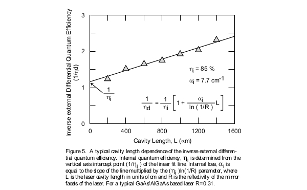
This parameter is a measure of the efficiency of a laser in converting electron-hole pairs (injected current) into photons (light) within the laser diode structure. For example, if the internal quantum efficiency is determined to be 75 percent, then 75 percent of electron-hole pairs are converted into photons and the remaining 25 percent into other forms of energy such as heat. The symbol ηi is used to represent this fundamental property. Unlike the external differential quantum efficiency, the internal quantum efficiency is independent of the geometrical properties of the laser device, such as the cavity length or the stripe width. As a result, it is the proper parameter for comparison of the material quality of various lasers made from various semiconductor wafers. In order to do this, it is necessary to experimentally measure the external differential quantum efficiency of lasers of various cavity lengths, with the results tabulated as shown in Figure 4. The internal quantum efficiency is then determined by plotting the curve of inverse external differential quantum efficiency versus the cavity length as shown in Figure 5. The inverse of the intercept point of the linear fit line of the set of data points with the vertical axis is the internal quantum efficiency parameter, indicated in percentage form. Internal quantum efficiency is one of the main figures of merit that should be used in assessing the quality of the semiconductor wafer from which the laser diode is manufactured from. Internal quantum efficiency is related to external quantum efficiency through the relationship shown in the inset of Figure 5.
Note that there is a difference between internal quantum efficiency, ηi and external differential quantum efficiency, ηd. The internal quantum efficiency is a direct indication of the efficiency of a laser in converting electron hole pairs (injected current) into photons (light) within the laser diode structure. But remember that not all of the photons that are generated find their way out of the device; some of them are reabsorbed due to various internal loss mechanisms. As a result, the external differential quantum efficiency is an indication of the efficiency of a laser in converting electron-hole pairs (injected current) into photons emitted from the laser device (output light). The value of the external differential quantum efficiency is always smaller than the internal quantum efficiency.(ηd) / (ηi) is the ratio of number of photons emitted from the laser to number of photons generated within the laser.
Internal Loss:
As mentioned above, the internal quantum efficiency parameter is a measure of the fraction of electron-hole recombinations that result in optical photons inside the laser cavity (thus the term internal). However, partially due to internal losses (αi) of the laser waveguide, not all the photons generated inside the laser cavity find their way to the outside to contribute to the output light emitted from the mirror facet(s) of the laser diode. Thus the External Differential Quantum Efficiency value of any laser diode is always smaller than its internal quantum efficiency. The light that propagates through the laser diode cavity suffers from losses as is the case of light propagation in any optical waveguide. The internal loss is the parameter which corresponds to the loss of the optical wave. Its value is determined experimentally through measuring the slope of the linear fit line to the inverse of external differential quantum efficiency versus cavity length data points as shown in Figure 5.
Transparency Threshold Current Density:
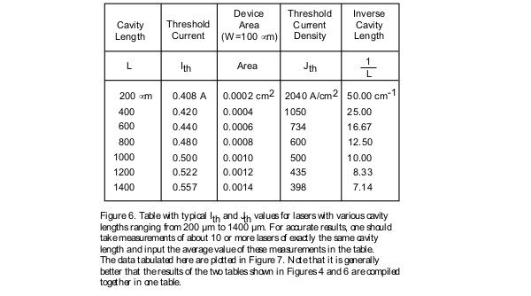
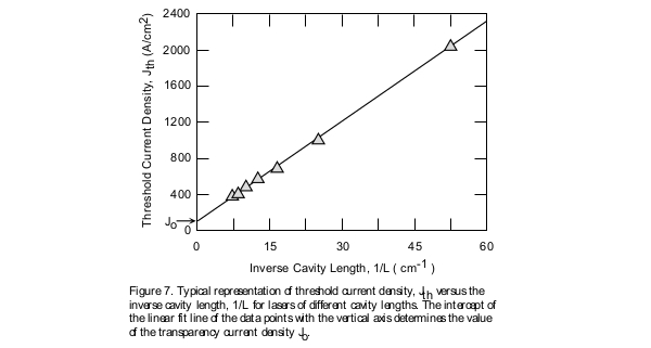
Another significant parameter that could be extracted from the data, experimentally measured and tabulated, in Figure 4, is the transparency threshold current density denoted by the symbol Jo. Threshold current density depends upon the cavity length of the laser diode. As a result it would not be accurate to compare the quality of one set of semiconductor wafers with the other using just the threshold current density parameter. Using the data tabulated in Figure 6 it is possible to extract a parameter that is independent of the device geometry. This is done through plotting the curve of threshold current density versus the inverse cavity length as shown in Figure 7. The intercept of the linear fit line of the data plotted in this curve with the vertical axis provides us with the transparency threshold current density value. This is the appropriate parameter that should be used in comparing the quality of various semiconductor wafers from which different lasers diodes are fabricated. Jo could be thought of as the threshold current density of a theoretical laser which has an infinitely long optical cavity with no loss of optical wave at its mirror facets.
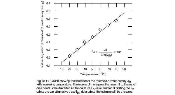
Characteristic Temperature:
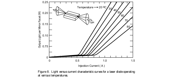
In most applications the ability of the laser diode to perform well at elevated temperatures is of great interest. This is specially of concern in the case of high-power laser diodes where the amount of heat generated causes the device temperature to rise significantly. As a result it is of utmost importance for the semiconductor crystal to be robust enough so as not to degrade due to device operation at high temperatures. The characteristic temperature of the laser diode, which is commonly referred to as To (pronounced T-zero) is a measure of the temperature sensitivity of the device. Higher values of To imply that the threshold current density and the external differential quantum efficiency of the device increase less rapidly with increasing temperatures. This translates into the laser being more thermally stable. In order to measure the characteristic temperature of a laser diode it is necessary to experimentally measure the L.I. curve of a laser at various temperatures. The results are then tabulated andthe To determined. Typically people perform these measurements at temperatures ranging from 15 degrees Celsius up to about 80 degrees Celsius, and at 5 or 10 degree increments. (Note that operating a laser that is not hermetically sealed, at temperatures significantly cooler than the room temperature, will result in water condensation on the device. This will cause damage to the laser diode due to electrical shorts.) Conventional AlGaAs lasers usually have To values above 120 degrees.
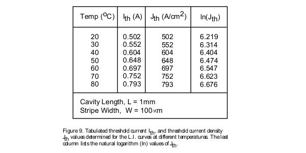
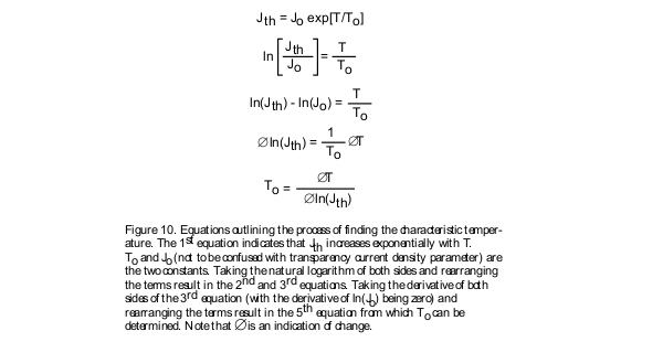
From these experimentally measured L.I. curves the characteristic temperature of the device is determined by plotting the Jth data points (or the Ith points) versus the temperature on a logarithmic scale and then measuring the slope of the linear fit line as shown in Figures 8, 9, 10, and 11.
Spectrum and Peak Wavelength of Emission:
The optical spectrum of laser diodes depends on the particular characteristics of the laser’s optical cavity. Most conventional gain or index guided devices have a spectrum with multiple peaks (Figure 12).
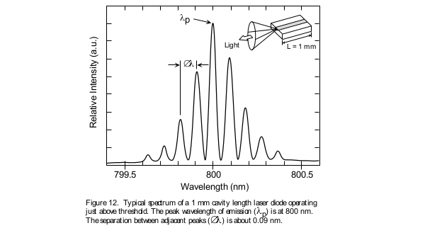
The number of spectral lines which a laser is capable of supporting is a function of the cavity structure, as well as the operating current. The result is that multimode laser diodes exhibit spectral outputs having many peaks around their center wavelength. The optical wave propagating through the laser cavity forms a standing wave between the two mirror facets of the laser. The period of oscillation of this curve is determined by the distance L between the two mirrors. This standing optical wave resonates only when the cavity length L is an integer number m of half wavelengths existing between the two mirrors. In other words, there must exist a node at each end of the cavity. The only way this can take place is for L to be exactly a whole number multiple of half wavelength λ/2. This means that L = m(λ/2), where λ is the wavelength of light in the semiconductor matter and is related to the wavelength of light in free space through the index of refraction n by the relationship λ = λo/n. As a result of this situation there can exist many longitudinal modes in the cavity of the laser diode each resonating at its distinc wavelength of λm = 2L/m. From this you can note that two adjacent longitudinal laser modes are separated by a wavelength of ∆λ = (λo)2 /2nL. For a typical GaAs/AlGaAs based laser n=3.5.
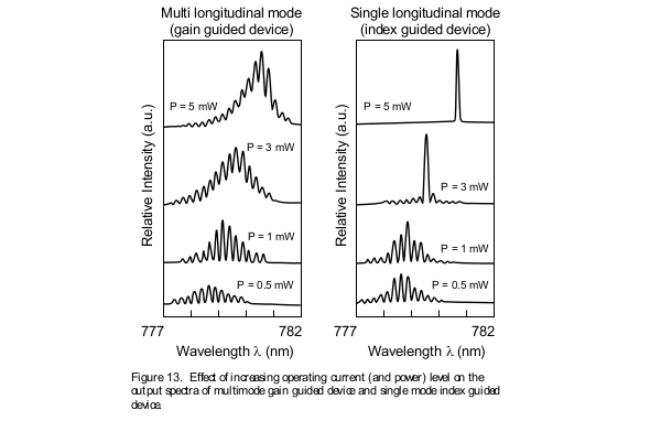
Unlike conventional laser diodes that display multi-mode spectra, single frequency laser diodes such as distributed feedback (DFB) and distributed bragg reflector (DBR) type of devices display a single well defined spectral peak. Figure 13 shows a comparison between these two spectral behaviors at various output power levels. Even single mode devices can support multiple modes at low output power. As the operating current is increased one mode begins to dominate until, beyond a certain operating power level, a single narrow linewidth spectrum appears.
Center Wavelength Changes with Temperature:
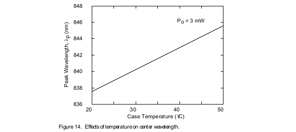
The center wavelength of a laser diode is directly proportional to its operating temperature. There is a linear relationship between temperature and center wavelength as shown in Figure 14. As temperature increases, so does the center wavelength of the laser diode. This characteristic is useful in spectroscopic applications, laser diode pumping of solid state lasers and erbium-doped fiber amplifiers, where the wavelength of emission of the laser diode can be accurately temperature tuned to the specific properties of the material with which the laser diode is interacting.
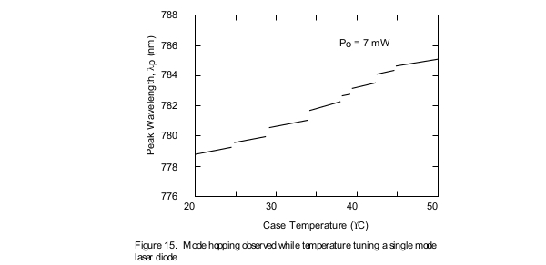
Mode Hopping:
Single mode lasers exhibit a phenomenon called mode hopping (Figure 15), in which the center frequency of the laser diode hops over discrete wavelength bands and does not show continuous tuning over a broad range. One can change the wavelength where the discontinuities take place by making small adjustments to the drive current. When selecting a specific laser diode for an application which requires a specific wavelength, such as spectroscopy, mode hopping must be taken into account when temperature tuning the device.
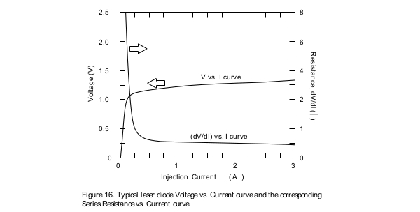
Dynamic Series Resistance:
The series resistance of the laser diode is typically determined through calculating the derivative of the voltage versus injection current characteristic curve of the device. One way of doing this is to use a computer program to determine the first derivative of the voltage versus current characteristic curve of the device that is obtained experimentally (Figure 16). High series resistance values for a laser diode could be the result of low quality metal ohmic contacts deposited on the two sides of the device. As a result, measurement of the series resistance value can be a means of assessing the quality of the metallic contacts deposited on the laser